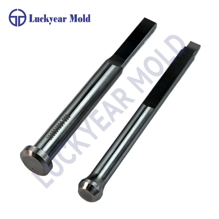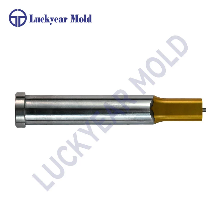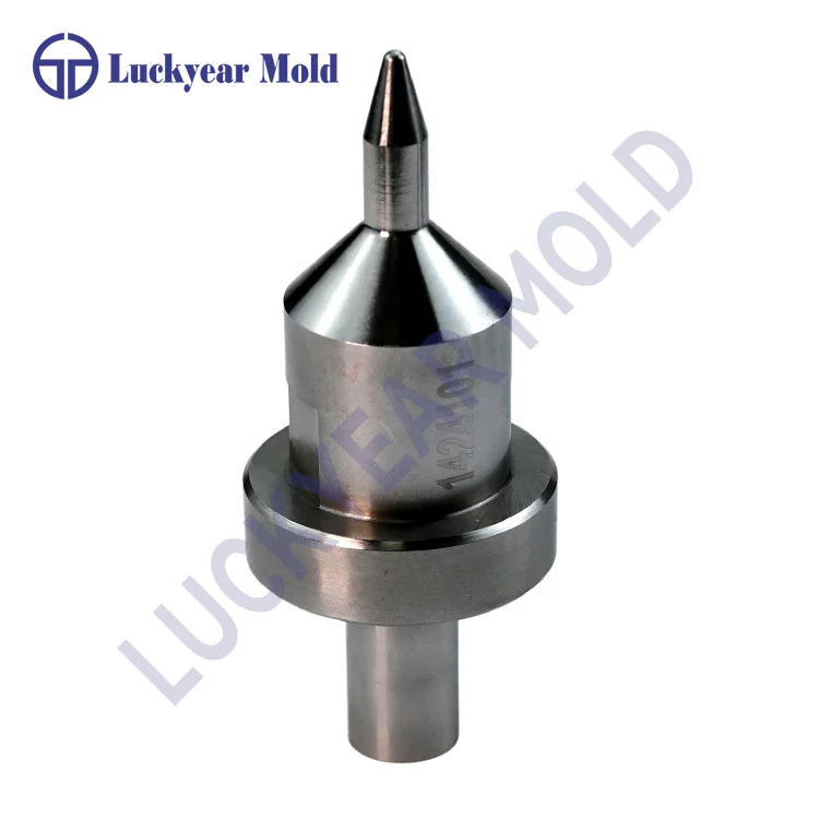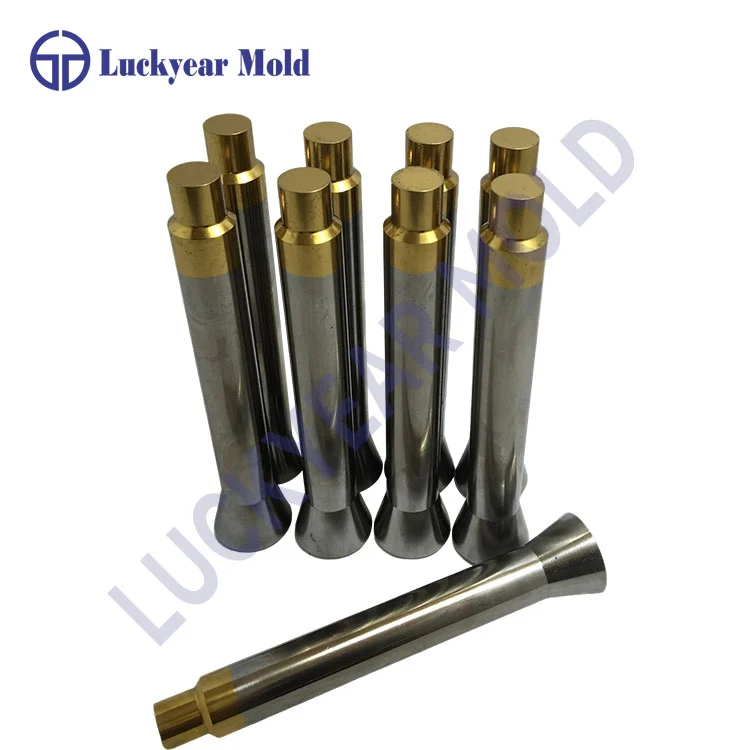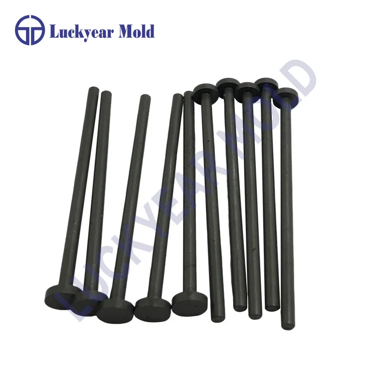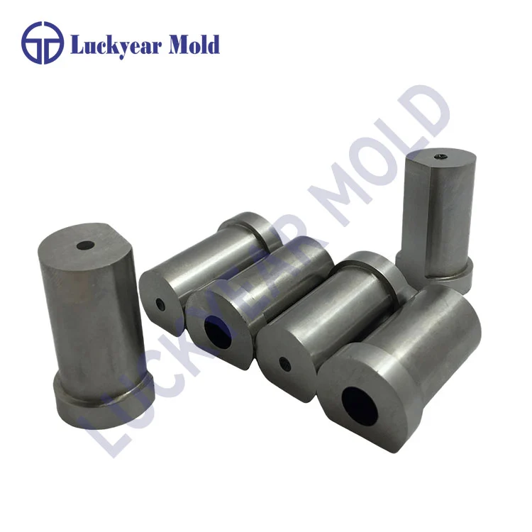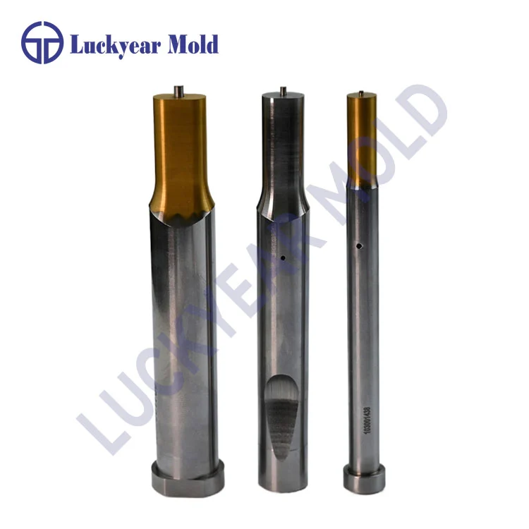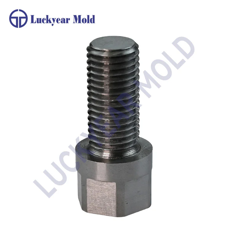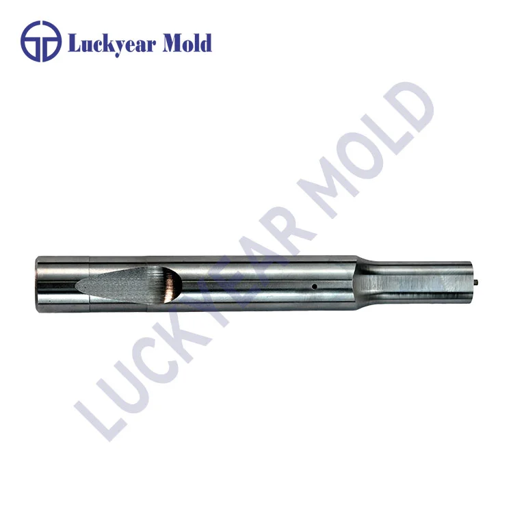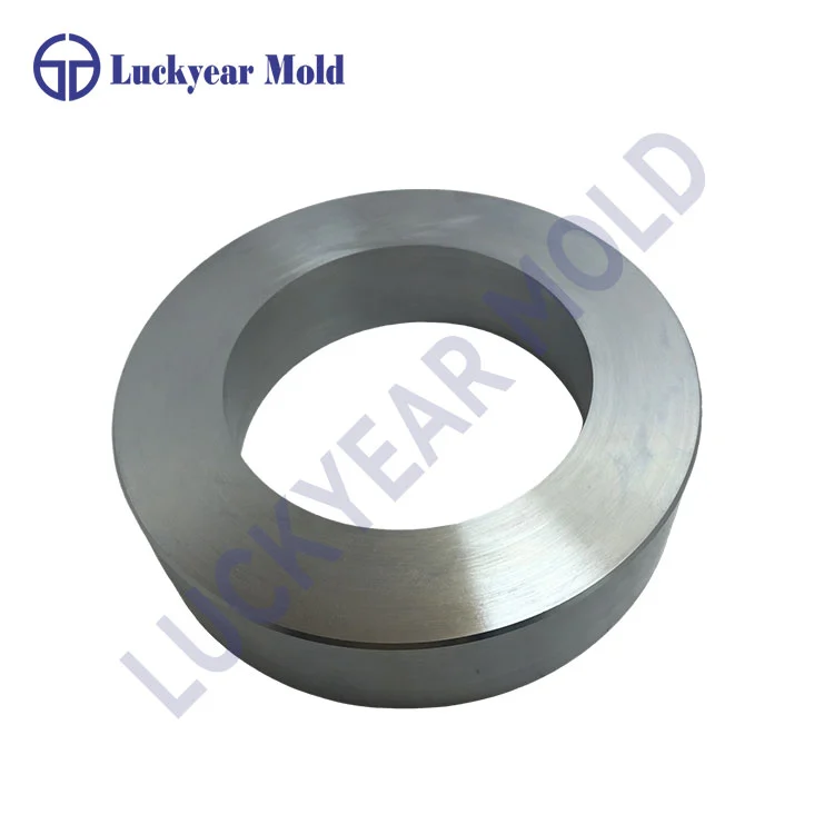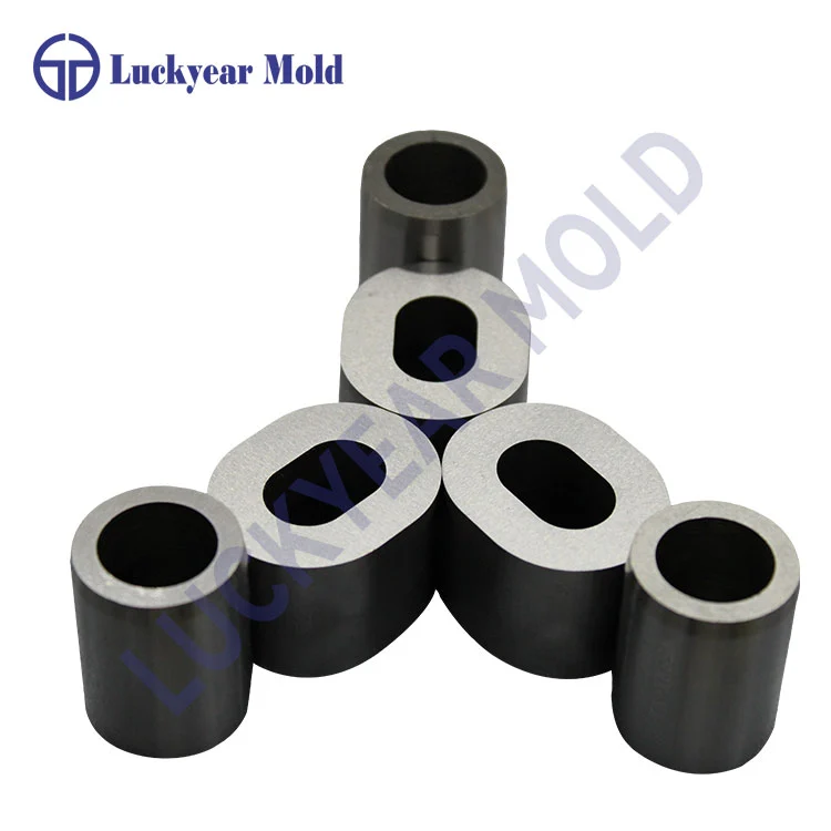
For operations demanding exceptional precision in blanking, punching, and forming, the correct jig and fixture components are non-negotiable. A DIN 9845 Type B die bush serves as a critical wear part, protecting the die plate from direct tool contact and ensuring consistent hole alignment over extended production runs. This robust guide bushing is engineered to withstand high radial forces and provide superior guidance for punches. Similarly, Die buttons DIN 9845 type B function as precision apertures for specific die applications, working in tandem with guide bushings to create a reliable and durable tooling system. Together, these components form the backbone of a high-performance press tool, directly impacting part quality, tool longevity, and overall manufacturing efficiency. Their standardized DIN dimensions ensure interchangeability and simplify the sourcing and maintenance process for toolmakers globally.
The DIN 9845 type B Drill Guide Bushing is distinguished by its specific dimensions and construction, which are meticulously defined by the Deutsches Institut für Normung (DIN) standard. This standardization guarantees that every bushing manufactured to this specification will deliver predictable performance and fit seamlessly into corresponding die sets or plates. Key to its design is the flange, which provides a positive stop during installation and helps to distribute load forces evenly. The precision-ground internal diameter offers minimal clearance for the punch, drastically reducing deflection and preventing premature wear on both the punch and the die plate. Manufactured from high-grade, through-hardened tool steel, the DIN 9845 type B Drill Guide Bushing is built for resilience, maintaining its dimensional stability and surface hardness even under continuous, high-stress stamping conditions.
The technical parameters of the DIN 9845 Type B bushing are critical for proper selection and application. Below are the core specifications:
| Nominal Bore (d1) mm | Flange Diameter (d2) mm | Overall Height (h1) mm | Flange Height (h2) mm | Recommended Fit in Die Plate (H7) |
|---|---|---|---|---|
| 10 | 18 | 16 | 5 | 18H7 |
| 12 | 20 | 16 | 5 | 20H7 |
| 16 | 25 | 20 | 6 | 25H7 |
| 20 | 30 | 25 | 8 | 30H7 |
| 25 | 38 | 28 | 8 | 38H7 |
Note: Dimensions are nominal. Tolerances on the bore (d1) are typically g6 or h6 for precise punch guidance, while the outside diameter (for press-fit) adheres to standard sliding or press-fit tolerances as per application requirements. Always consult engineering drawings for critical applications.